Your Cart is Empty



A device powers on but behaves oddly: no output, no switching, nothing responding the way it should. Many beginners start swapping parts at random, hoping to stumble onto the fix.
One of the most overlooked components in that troubleshooting chain is thetransistor, and testing one takes less than two minutes with a basic multimeter, no specialized equipment required.
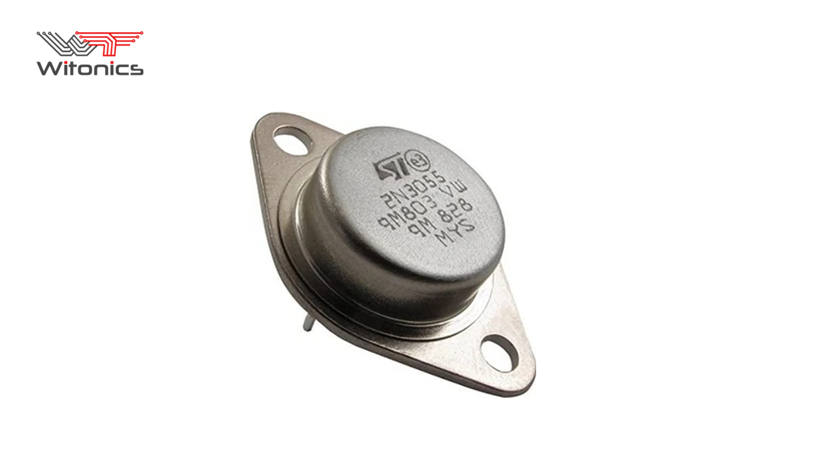
A transistor is a small semiconductor device used to switch or amplify electrical signals. It has three legs: the base, the collector, and the emitter. In simple terms, a small current or voltage applied at the base controls a much larger current flowing between the collector and emitter.
When a transistor fails, it typically fails in one of two ways: it shorts internally, allowing current to flow when it shouldn't, or it opens internally, blocking current when it should flow. Both failures produce very different symptoms in a circuit, but both are equally easy to catch with a simple multimeter test.
A transistor is essentially two diodes sharing a common terminal, the base. In anNPN transistor, current flows from collector to emitter once the base is forward-biased relative to the emitter. In a PNP transistor, the relationship is reversed. Because of this diode-like internal structure, most multimeters can test a transistor using their diode test mode, without needing a dedicated transistor tester or curve tracer.
Just a digital multimeter with a diode test setting, marked with a diode symbol on the dial. Analog multimeters can sometimes test transistors too, but the diode-mode approach on a digital meter is far more consistent and beginner-friendly.
You'll also need to know which lead is the base, collector, and emitter before you begin; check the datasheet for the exact part number rather than guessing based on leg position, since pinouts vary between manufacturers and packages. If you're building out a fuller repair toolkit beyond just a meter, our essential tools forautomotive electrical repairs guide covers what else is worth having on hand.
1. Set the multimeter to diode test mode.
2. Place the red probe on the base and the black probe on the emitter. A healthy transistor shows a voltage-drop reading, roughly 0.5–0.7V for silicon devices. No reading at all means an open junction.
3. Move the black probe to the collector, keeping the red probe on the base. You should see a similar voltage-drop reading.
4. Reverse the probes on both of those pairs, red and black swapped. You should get no reading (displayed as OL, or open line) in either reversed direction.
5. Finally, test collector to emitter directly in either probe order. A healthy transistor shows no continuity at all between these two legs when the base isn't involved.
|
Test |
Good Transistor |
Bad Transistor |
|
Base–Emitter (forward) |
~0.5–0.7V |
No reading or 0V |
|
Base–Collector (forward) |
~0.5–0.7V |
No reading or 0V |
|
Base–Emitter (reverse) |
No reading (OL) |
Reading present |
|
Collector–Emitter |
No reading either way |
Reading present |

Testing a transistor while it's still soldered onto a board is possible, but the results aren't always reliable, since surrounding resistors,capacitors, and other components can create parallel paths that skew your readings.
Whenever you get an ambiguous or unexpected result, desolder at least one leg, ideally the base, before retesting. This isolates the transistor from the rest of the circuit and gives you a much cleaner, trustworthy reading. If you're testing several suspect parts on a busy board, isolating one at a time also prevents you from misdiagnosing a good part as bad simply because of its neighbors.
→ Testing a transistor while it's still connected to a live, powered circuit: always test with the power source disconnected.
→ Assuming the pinout based on leg position alone instead of checking the actual datasheet for that part number.
→ Treating one good reading as proof the transistor is fine, without also checking for shorts in the reverse direction and across collector-emitter.
→ Forgetting that Darlington transistors and some power transistors show slightly different voltage-drop values due to their internal structure, which is normal and not necessarily a fault.
A: You can try, but nearby components may skew the reading. For a reliable result, desolder at least one leg, ideally the base, before testing.
A: Diode test mode, marked with a diode symbol on the dial. Avoid relying on resistance/ohms mode, which can give less consistent results.
A: OL, or open line, means no continuity was detected in that direction , the expected, healthy reading for a reverse-biased junction.
A: Check the part number against its datasheet. As a shortcut, an NPN gives readings with the red probe on the base; a PNP gives readings with the black probe on the base.
A: Yes. This test only catches shorts and opens, not weak gain or slow switching speed. If symptoms continue after a passing test, the part may still be underperforming and worth replacing anyway.
If any junction shows a short, meaning it reads in both directions, or an unexpected open where a reading should exist, the transistor has failed and needs replacing. Always replace with the exact part number where possible or a confirmed equivalent with matching voltage, current, and gain specifications. At Witonics, browse our range ofTransistors and Diodes to find the right replacement for your repair.
Testing a transistor isn't complicated once you understand what you're actually checking: two diode junctions and one open path between collector and emitter. A five-minute test with a meter you probably already own can save you from replacing an entire board over one small, inexpensive part.
Need a replacement part? Shop Transistors and Diodes atWitonics